
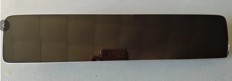
2026-model-year HU7 display
Qty 1The driver-facing MBUX 3 screen replaces the older display experience and presents the new infotainment interface. The source identifies a 2026-model-year unit; it does not state the screen size.
Mercedes-Benz G-Class · 2019–2024
For 2019–2024 G-Class owners, this conversion moves the infotainment from COMAND NTG5.5 toward MBUX 3 HU7, while updating the dashboard controls and centre console toward a W465-style cabin. The complete illustrated list shows how the display, control computers, cameras, wiring, switches, trim and saddle console contribute. Check the exact configuration, coding and retained functions by VIN before ordering.
The parts sheet calls the display a “26款” HU7 unit: that means 2026 model year, not a 26-inch screen. Exact parts and installation requirements must be confirmed for your vehicle by VIN.
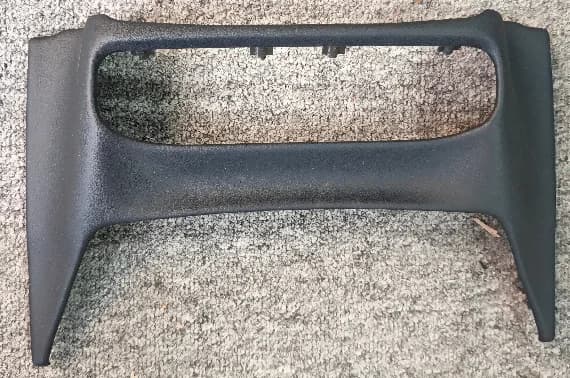
The cabin transformation
These OWNSILENT case-study photos show an original G-Class cabin and a completed G-Class interior example. The finished-cabin image is a visual reference, not a claim that this exact MBUX 3 HU7 kit is installed in that vehicle.
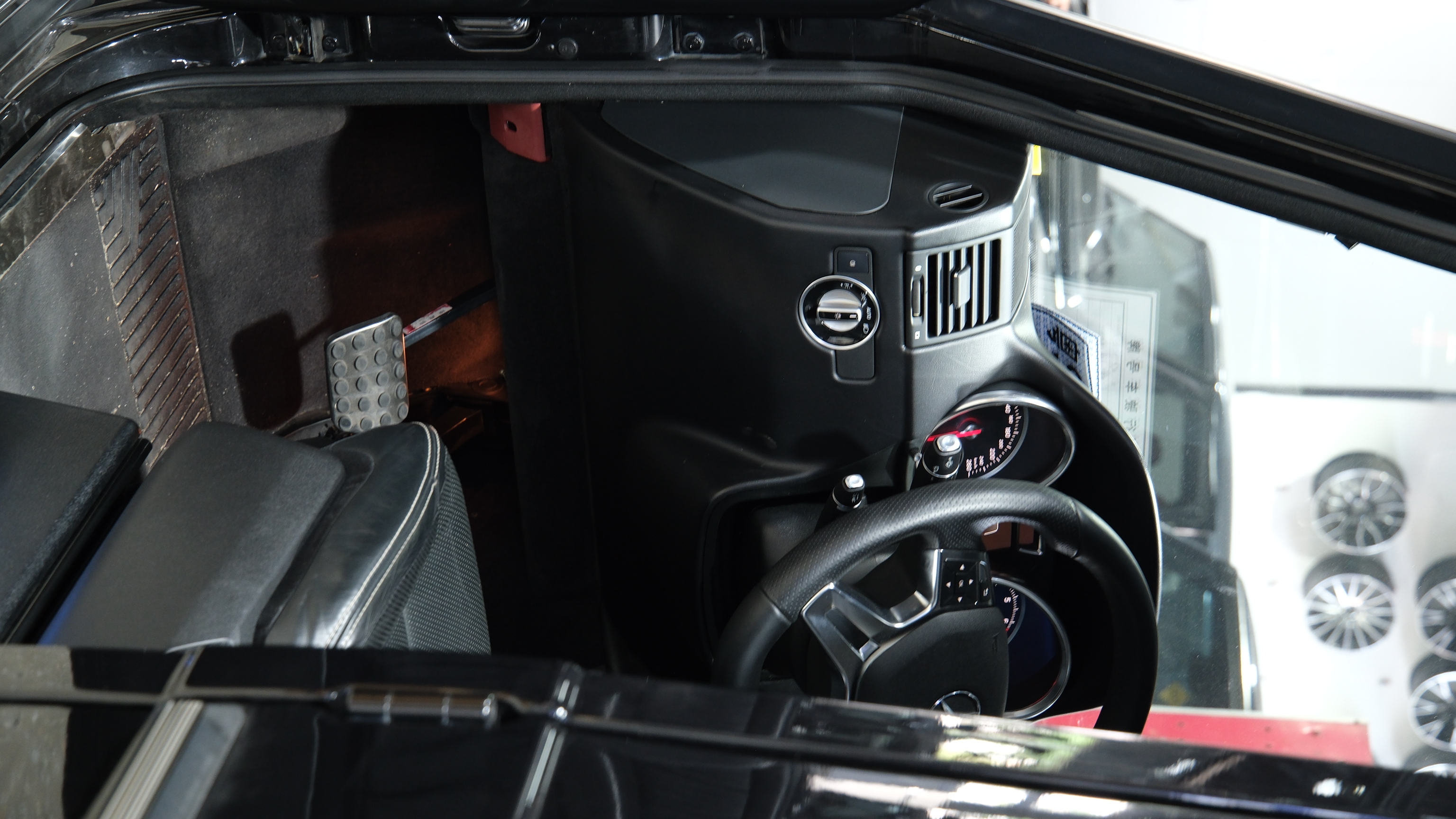 BEFORE · ORIGINAL CABIN
Real pre-conversion cabin reference from the OWNSILENT G-Class installation case study.
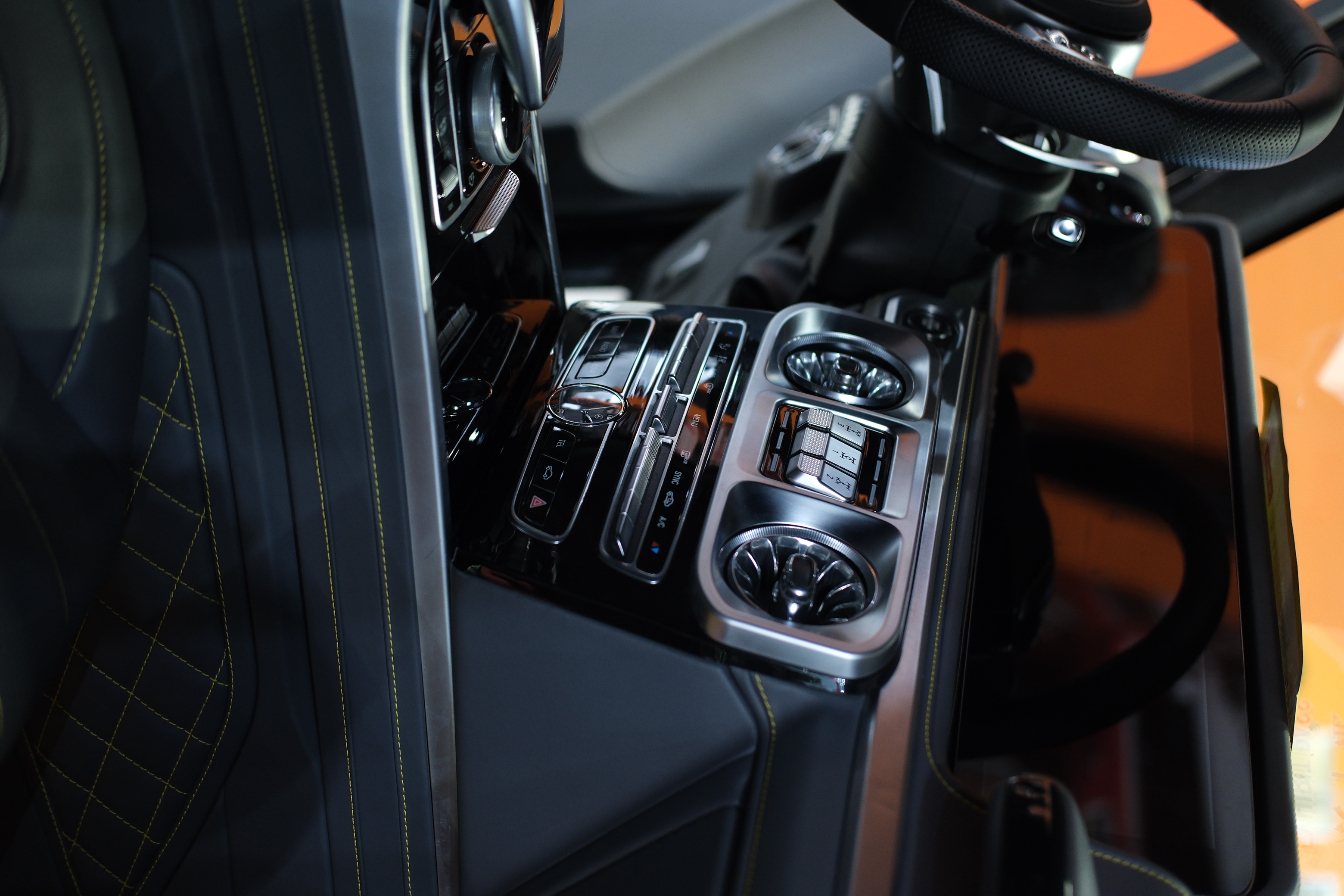 COMPLETED · CABIN EXAMPLE
Real completed G-Class interior reference. This photo is from a separate cabin project and does not verify installation of this exact HU7 kit.
Infotainment
COMAND NTG5.5 → MBUX 3 HU7 display and control hardware.
Cabin layout
W465-style dashboard trim, switches and 465 saddle console pieces.
Vehicle connections
Listed modules and looms support cameras, parking sensors, antennas and audio.
One conversion, one parts list
Start with the system you want to understand, then review each named part, quantity and photo.
Refreshes the display and supporting control hardware; exact modules and coding depend on the vehicle.
Jump to partsSection 2Connects the listed cameras and parking sensors through their modules; operation depends on matching equipment and configuration.
Jump to partsSection 3Links the screen, modules, switches, cameras, antennas, USB and amplifier into the selected retrofit setup.
Jump to partsSection 4Changes the visible vent and switch layout and supplies selected climate, lighting and vehicle-control pieces.
Jump to partsSection 5Updates the centre-console shape and fittings, including cupholder, USB, lighter and ambient-light pieces.
Jump to partsSection 6Covers adapt the listed dashboard sections; brackets mount the HU7 and instrument computers.
Jump to partsBefore you order
Send the VIN, model year and clear photos of the current dashboard and console.
Ask the team to confirm the exact part numbers, quantities and any optional items in writing.
Confirm coding, retained functions, installation scope, price and shipping before payment.
The supplied parts list, explained
Names and quantities follow the supplied sheet. Each description explains the part’s role in the cabin or supporting systems. Where a source photo shows related parts together, it is reused for those entries; one cable has no separate photo.
Refreshes the display and supporting control hardware; exact modules and coding depend on the vehicle.
The driver-facing MBUX 3 screen replaces the older display experience and presents the new infotainment interface. The source identifies a 2026-model-year unit; it does not state the screen size.
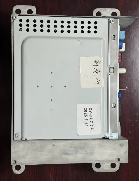
The HU7 computer runs the infotainment platform and links the display with the listed controls. The source sheet requires this unit to be matched to the vehicle VIN.
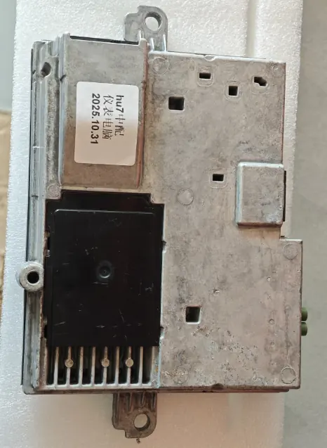
This computer supports the digital instrument display. It must be matched to the cluster and vehicle electronics, with any required programming confirmed.
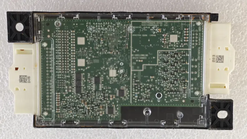
The lock and ignition module connects the updated control setup with the vehicle ignition and locking architecture. Confirm its exact role and coding for the VIN.
Connects the listed cameras and parking sensors through their modules; operation depends on matching equipment and configuration.
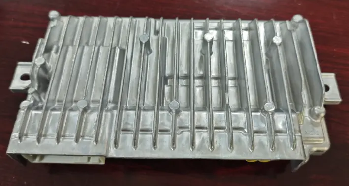
This module coordinates compatible camera and parking-system signals for the listed 360 setup. Camera pairing, vehicle equipment and any coding need confirmation.
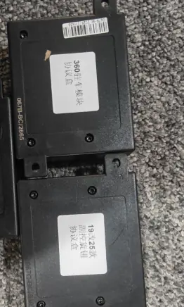
This protocol interface is listed alongside the 360 parking module to support its connection within the retrofit. Confirm the exact module pairing in the written kit scope.
The source shows this together with the button-and-knob protocol box.
This interface box is paired with the button and rotary-knob controls, linking those driver inputs to the selected control setup.
The source shows this together with the 360 parking module protocol box.
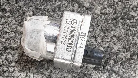
Four listed cameras cover front, rear, left and right positions and provide the camera views used by the selected parking system. Confirm each connector and position.
This camera supplies the listed driving-recorder video input. Confirm its recording system, connection and activation requirements.
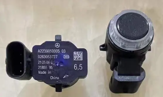
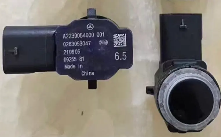
These ten straight-connector sensors detect nearby obstacles for the parking-assist system. Match the connector and sensor configuration to the vehicle.
The source photo is shared with the angled-connector sensor entry.
These two angled-connector sensors provide additional parking-assist detection where the vehicle layout calls for the angled type. Confirm position and connector.
The source photo is shared with the straight-connector sensor entry.
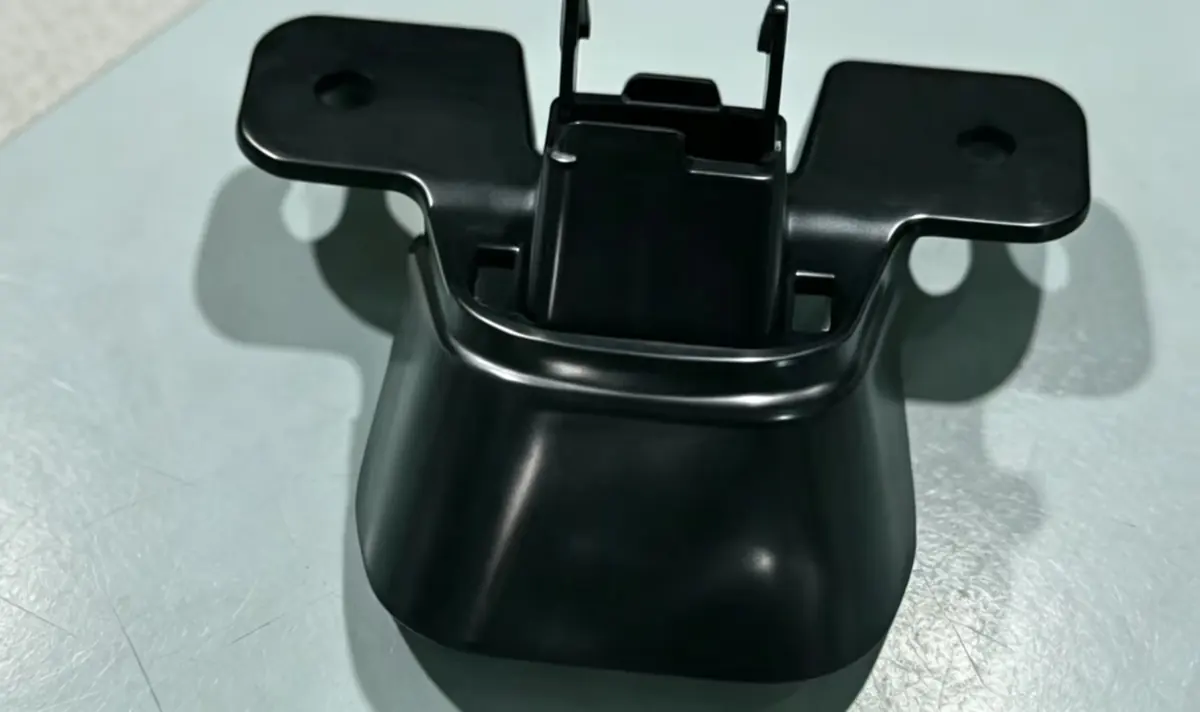
This bracket provides the mounting point for the front-bumper camera. The source sheet does not state a quantity; confirm location and fit.
Links the screen, modules, switches, cameras, antennas, USB and amplifier into the selected retrofit setup.
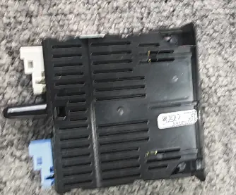
This USB interface box provides the listed USB connection point for the HU7 system. Confirm the supported ports and location for the selected console.
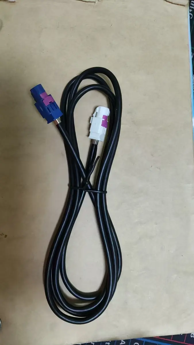
This lead connects the HU7 USB box to its matching harness. Check both connector ends before installation.
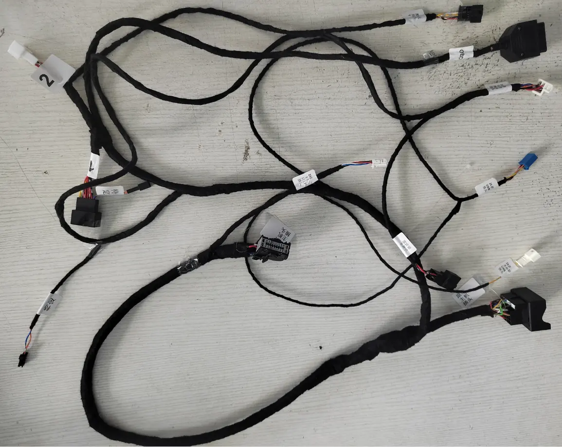
This main loom links the HU7 head unit and instrument system so the two updated cabin electronics can work together. The correct loom depends on vehicle equipment.
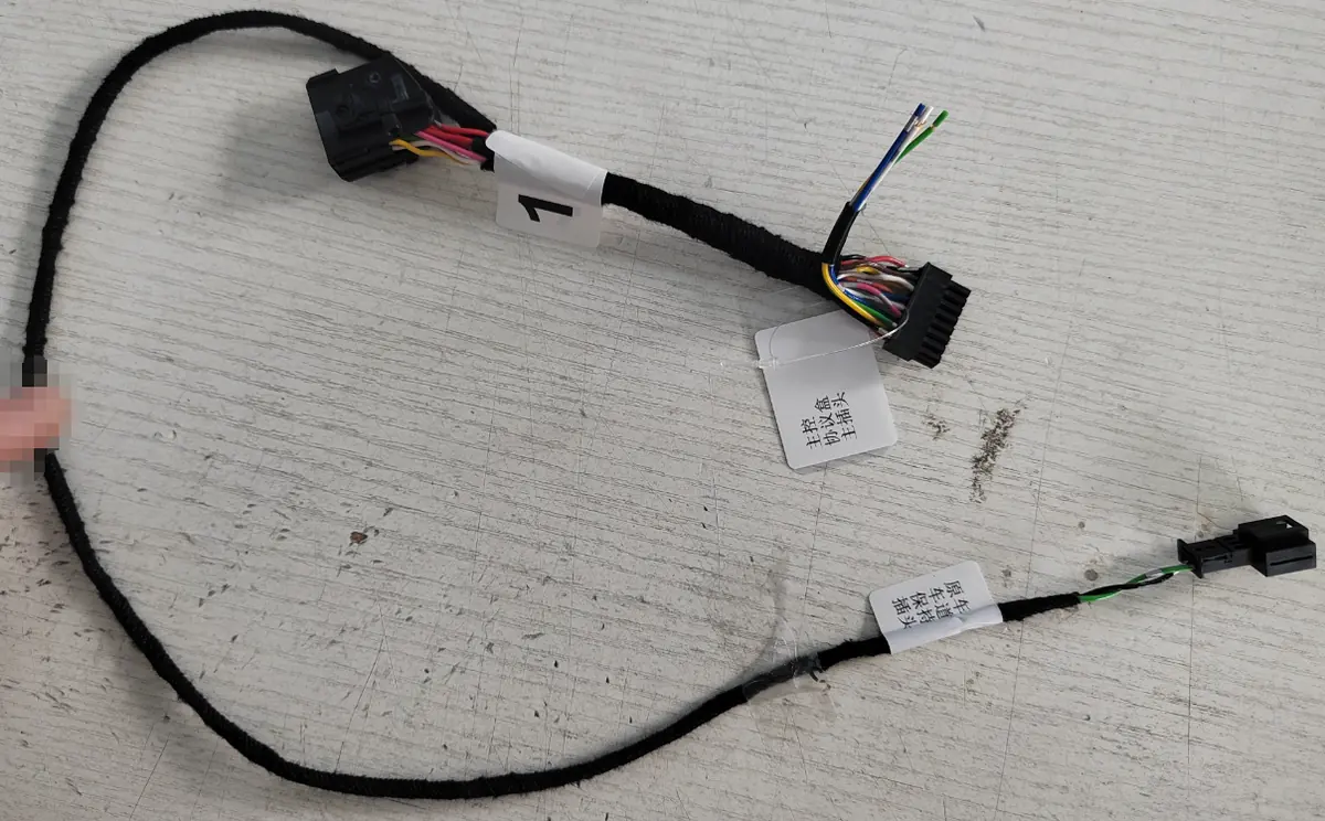
This lead connects the master-control protocol box to its matching retrofit components. Confirm the box version and cable ends as a set.
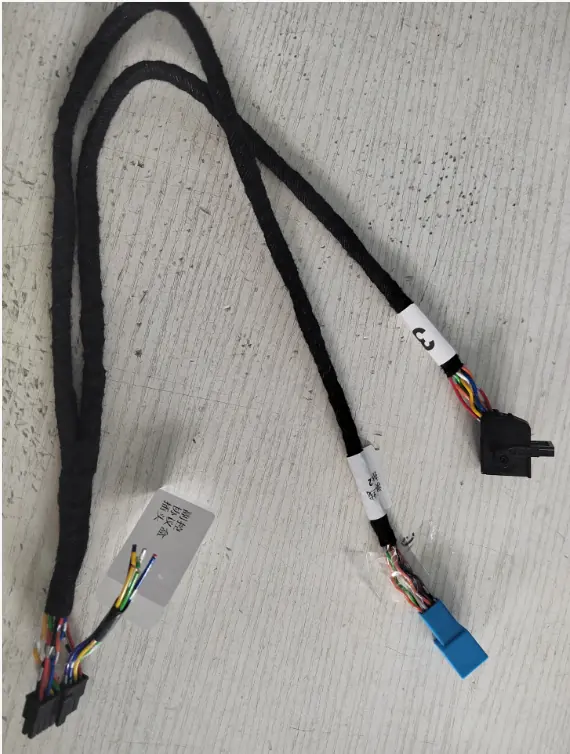
This lead connects the auxiliary protocol box into the retrofit wiring. It must match the selected box and vehicle loom.
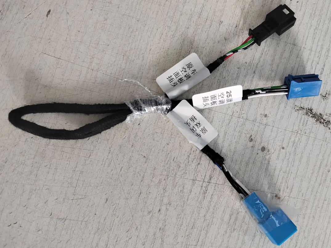
This wire connects the air-conditioning switch to the retrofit system, supporting the revised climate-control area. Confirm connector and routing.
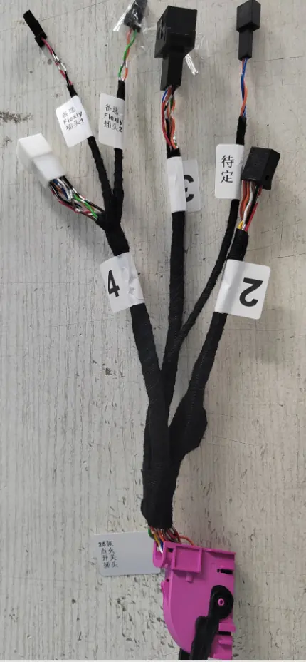
This harness connects the lock computer and ignition switch within the retrofit. Confirm the vehicle-specific connector and any required coding.
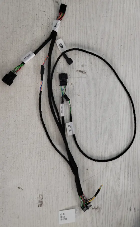
This cable links the parking module with its protocol box so the listed camera and sensor components can communicate through the chosen setup.
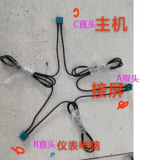
This video lead carries the signal between the listed video components. Confirm the source, destination and connector in the installation plan.
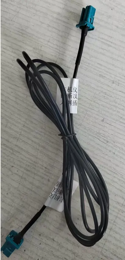
This Ethernet lead provides the listed diagnostic connection for setup or communication with compatible modules. Confirm its intended endpoint.
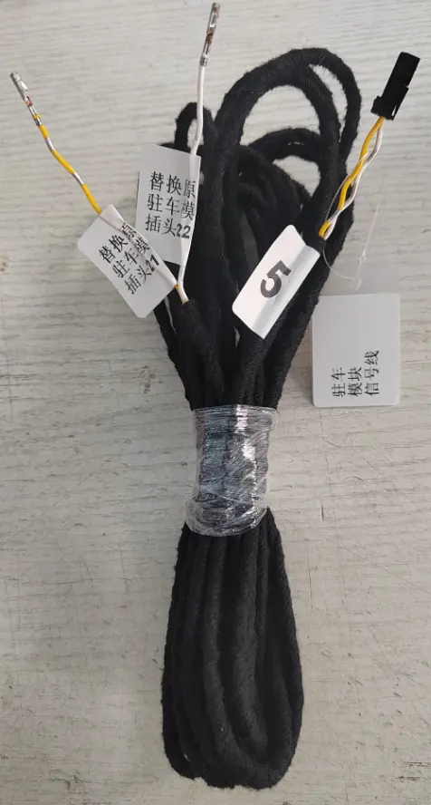
This signal cable connects the parking module to the corresponding vehicle or retrofit circuit. Confirm routing and connector against the VIN-matched plan.
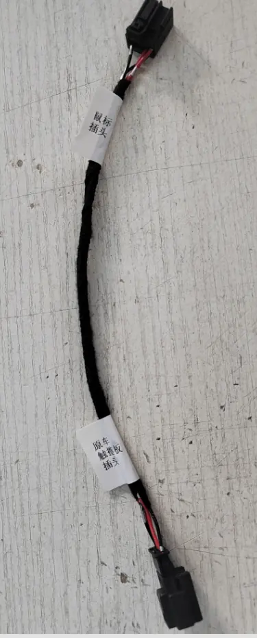
This adapter connects the cabin mouse/controller to the retrofit wiring, allowing the selected controller to operate with the new system.
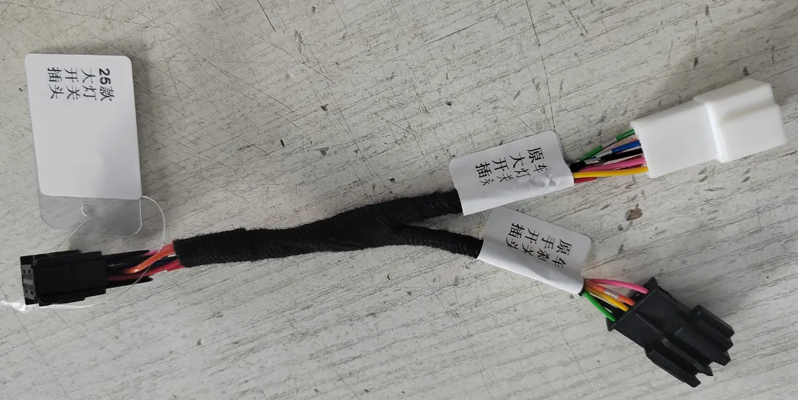
This harness connects the updated headlight switch to the vehicle wiring. Confirm switch version, connector and retained lighting functions.
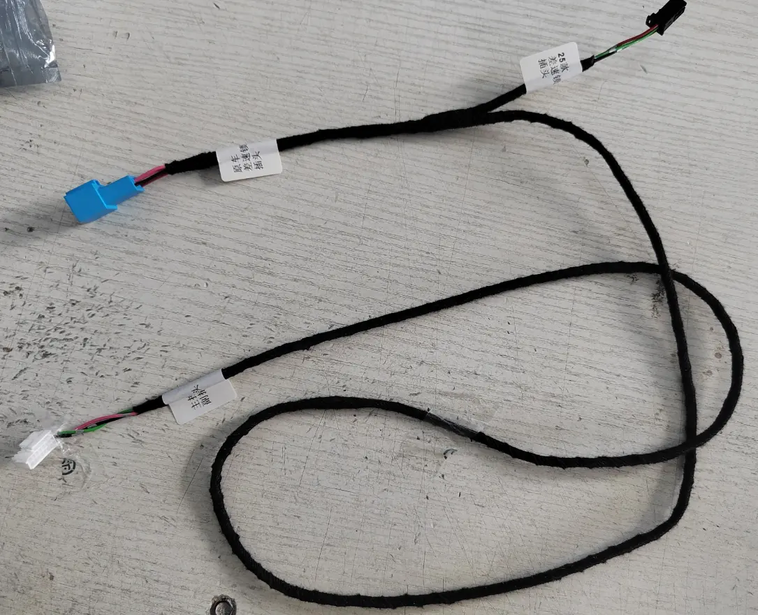
This lead connects the differential-lock switch controls to the vehicle system. Confirm the supported lock functions and wiring for the exact G-Class.
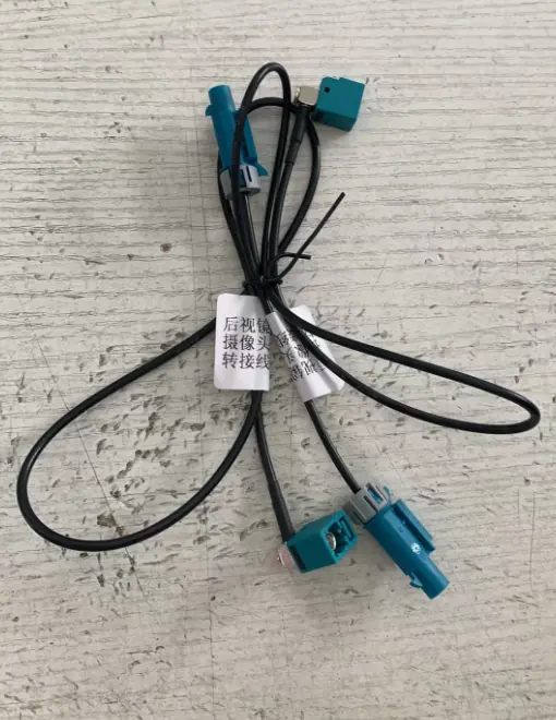
These two 50 cm adapters provide the listed connection from the rear-view-mirror camera area to the retrofit loom. Confirm camera type and routing.
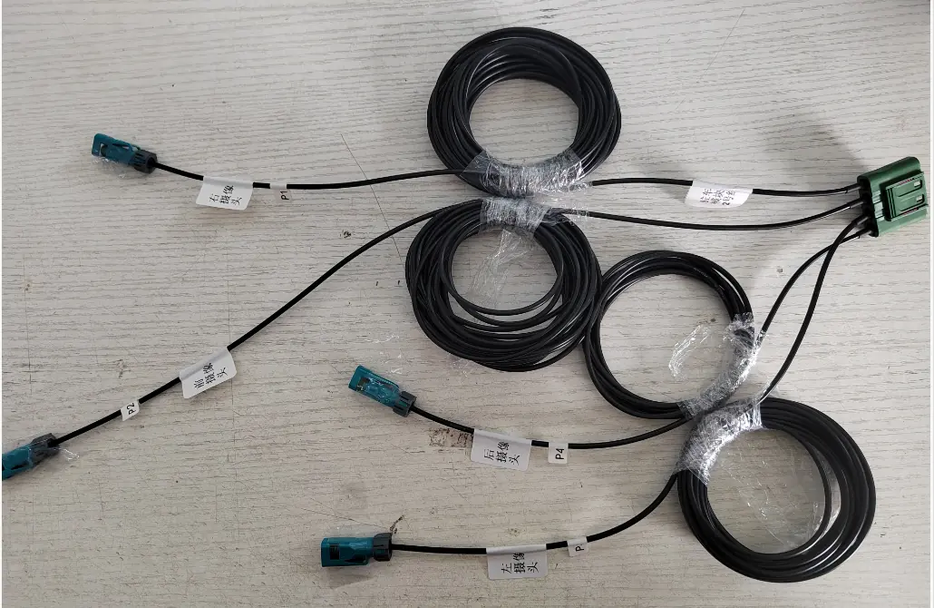
Parking-module line 2 is one of the numbered connections in the supplied loom. Its exact endpoint must be matched to the kit wiring diagram.
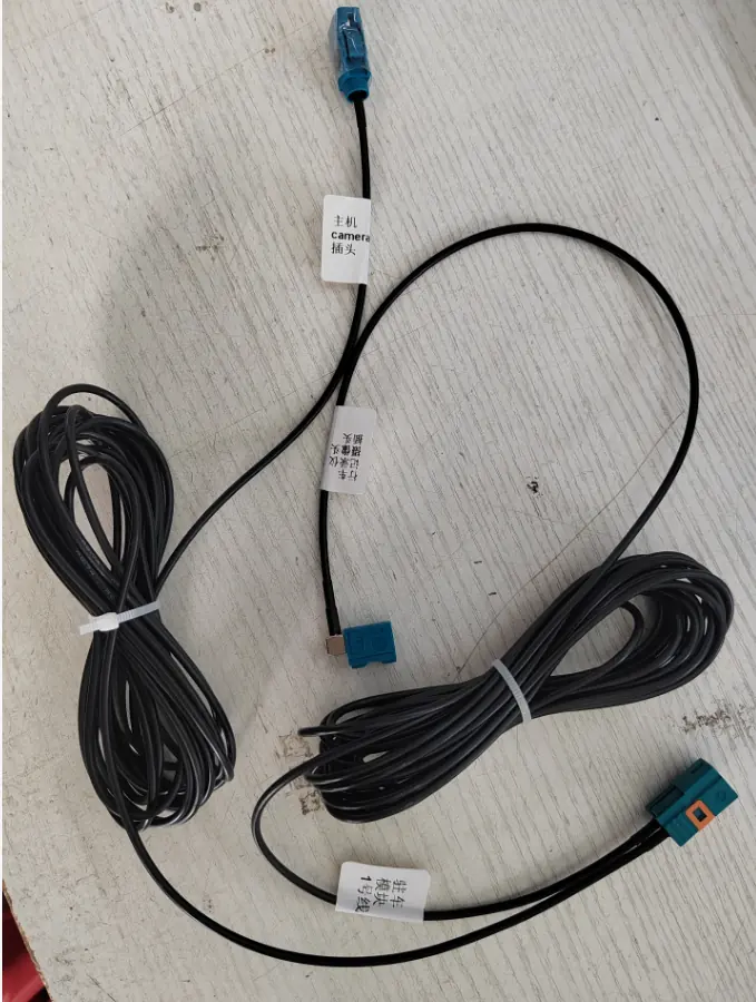
Parking-module line 1 is one of the numbered connections in the supplied loom. Its exact endpoint must be matched to the kit wiring diagram.
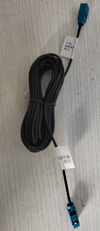
This five-metre data cable links the listed amplifier with the retrofit system. Confirm the amplifier version and route through the cabin.
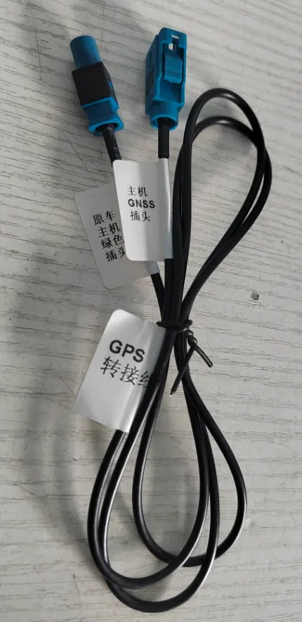
This one-metre adapter connects the GPS antenna path to the HU7 setup. Confirm the antenna type and connector.
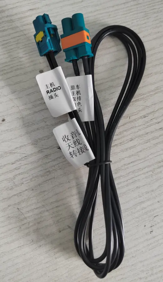
This adapter connects the vehicle radio antenna to the selected infotainment unit, supporting radio reception when the connector and antenna are compatible.
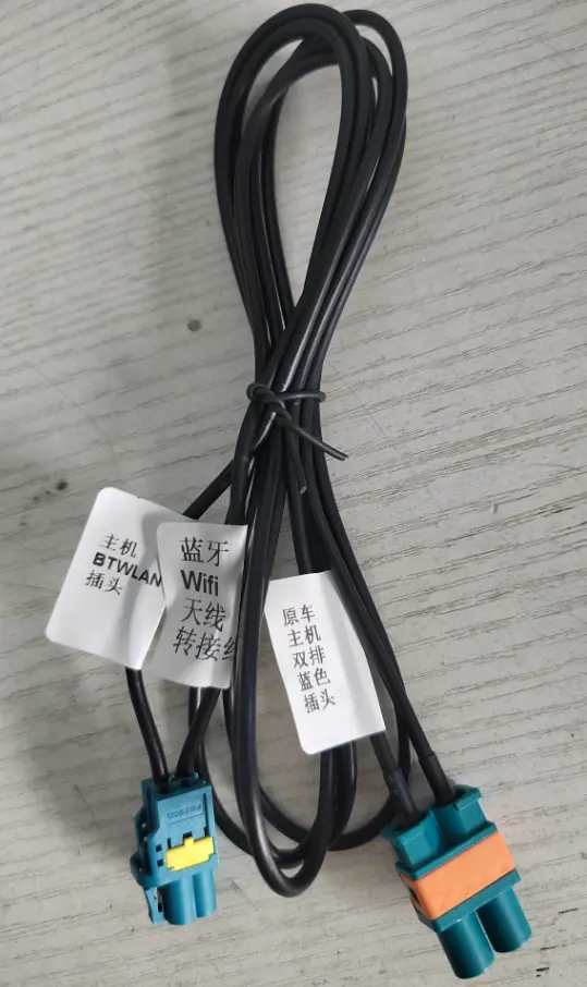
This adapter connects the listed Bluetooth/Wi-Fi antenna path to the HU7 system. Confirm the antenna version and connector before installation.
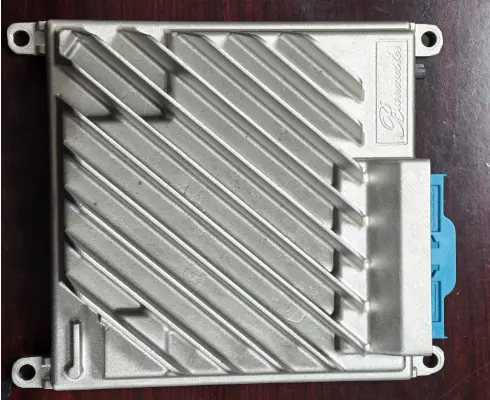
The amplifier boosts the audio signal for the connected cabin audio system. Confirm speaker and amplifier compatibility and whether the quoted setup includes all required audio components.
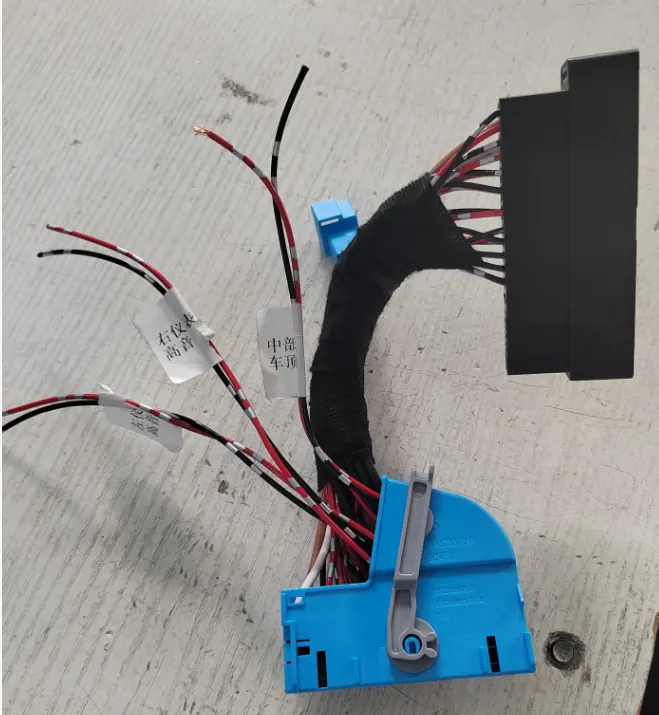
This lead adapts the amplifier connection to the retrofit harness. It must match the selected amplifier and loom.
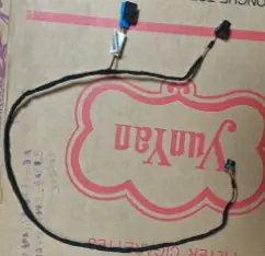
This extension carries the screen ambient-light connection to the required point in the revised layout. Confirm connector and route.
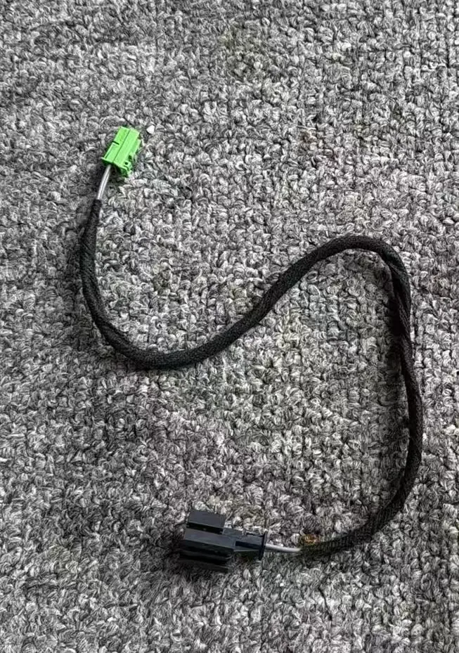
This extension carries the saddle-console antenna-amplifier connection to its required location. Confirm antenna, amplifier and cable versions.
This extension is listed for the lane-change-assist switch. The source notes it may not be needed with a factory-screen replacement; verify for the chosen setup.
The supplied sheet does not show a separate photo for this cable.
Changes the visible vent and switch layout and supplies selected climate, lighting and vehicle-control pieces.
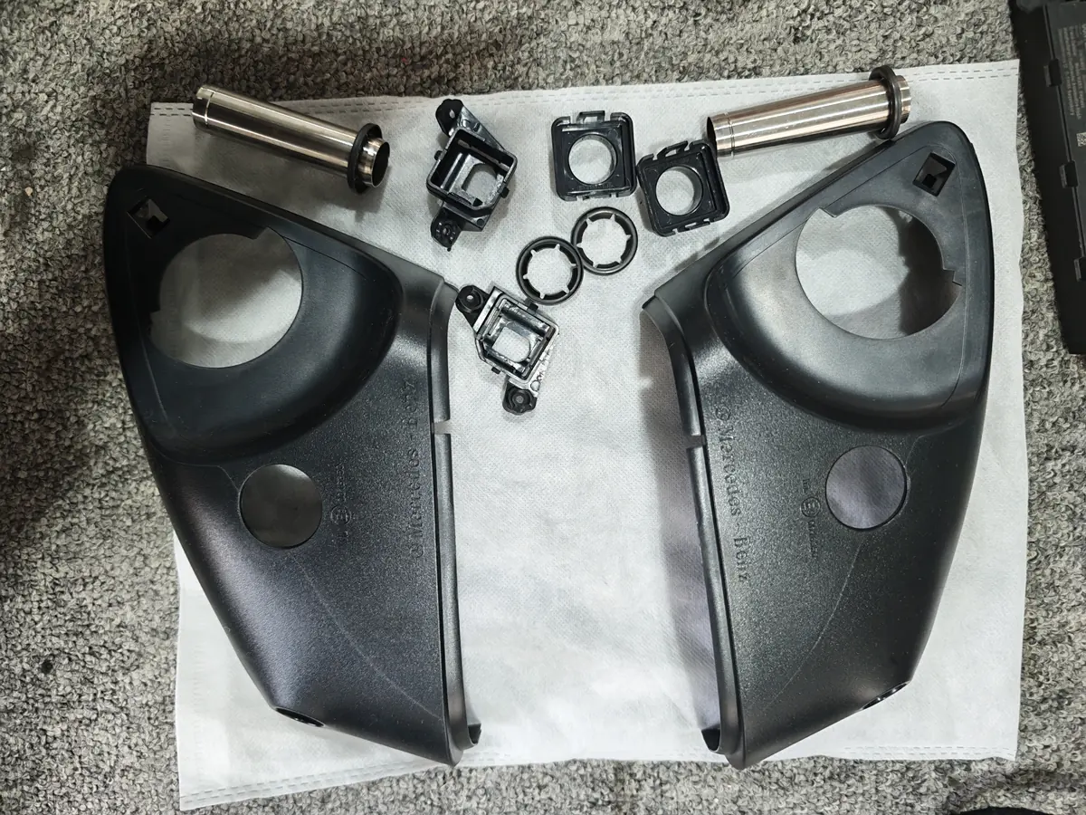
This pair of lower mirror shells finishes the mirror housing for the selected conversion. The source notes that the required version depends on whether the windscreen is changed.
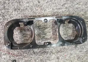
This base supports the climate-control panel within the revised dashboard area. Match its openings and mounting points to the selected switch panel.
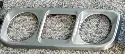
This silver-brushed panel changes the visible finish around the dashboard air vents while preserving the vent openings. Confirm trim and panel fit together.
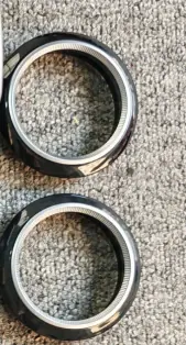
These two rings finish the dashboard vent openings and align with the listed vent panel. Confirm the finish and fit as a set.
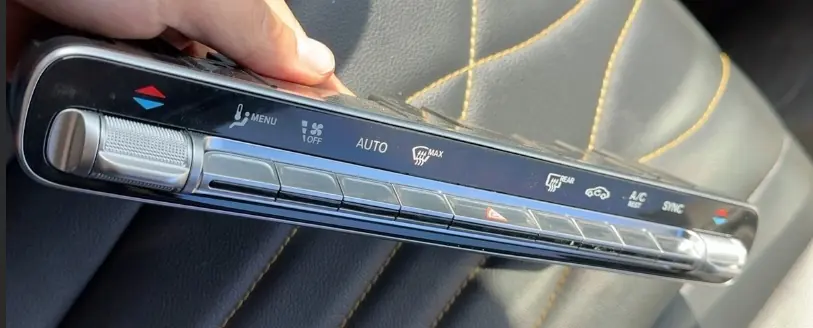
This climate switch operates the listed air-conditioning controls, but the source specifies no airflow-direction control. Confirm the functions you need to retain.
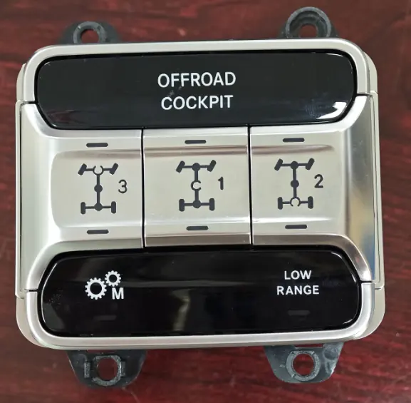
This switch panel provides the listed differential-lock controls in the revised dashboard layout. Confirm the vehicle's supported lock functions and coding.
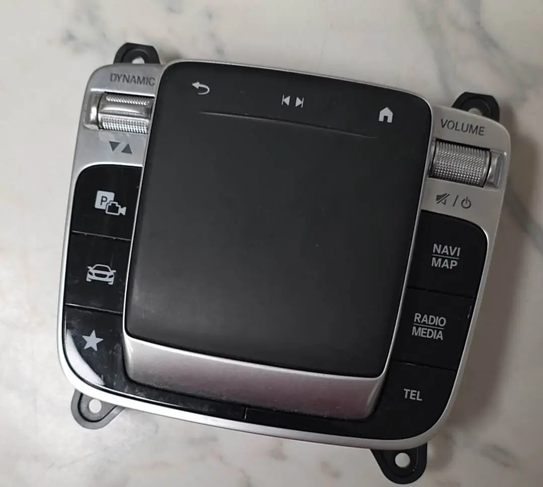
This cabin controller gives the driver a physical way to navigate the infotainment interface. The source says its original lettering is retained.
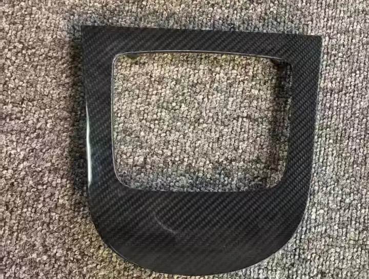
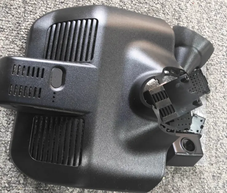
This housing finishes the interior mirror assembly. The required version depends on whether the windscreen is changed.
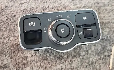
This 2026-model-year switch supplies the listed headlight controls in the refreshed layout. Confirm markings, connector and operation for the vehicle.
Updates the centre-console shape and fittings, including cupholder, USB, lighter and ambient-light pieces.
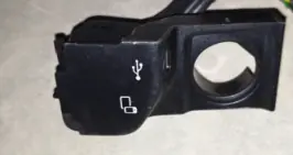
This USB port places a connection point in the front cupholder area. The source sheet does not state a quantity; confirm fit and wiring in the quote.
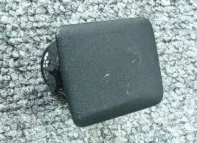
This socket provides a rear power outlet within the saddle-console area. Confirm its matching holder and wiring are included.
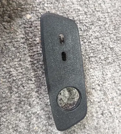
This holder secures the rear lighter/power socket in the saddle-console assembly. It should be checked with the selected socket and console base.
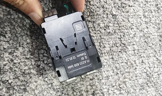
This rear USB port adds a connection point at the saddle console. Confirm the required harness and supported charging/data function.
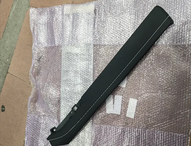
This left-side console cover finishes the saddle-console edge and includes the listed ambient-light element. Confirm side and lighting connection.
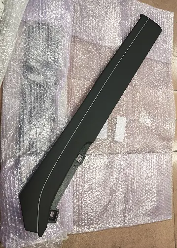
This right-side console cover finishes the opposite saddle-console edge and includes the listed ambient-light element. Confirm side and lighting connection.
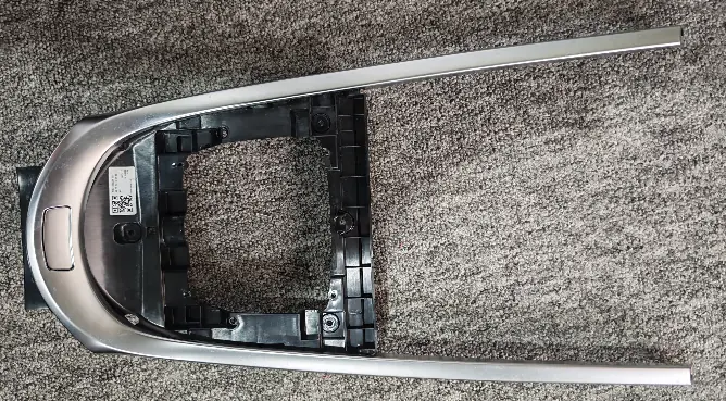
This chrome accent finishes the saddle-console surface and helps the console match the selected trim specification.
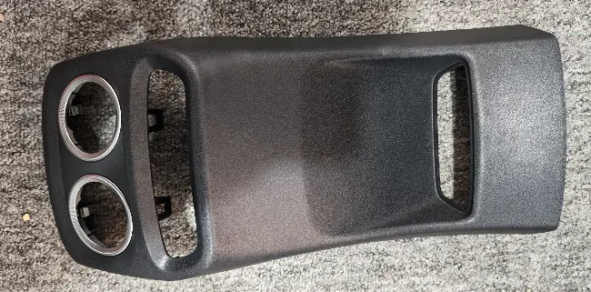
This panel closes the rear of the saddle-console assembly. Confirm its mounting points and finish with the console base.
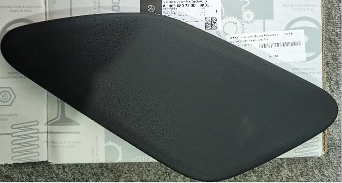
This left diamond-pattern panel forms part of the saddle-console side finish. Confirm side, pattern and trim match the right panel.
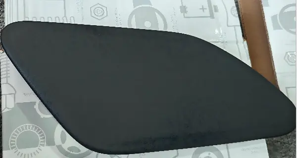
This right diamond-pattern panel completes the opposite side of the saddle-console finish. Confirm side, pattern and trim match the left panel.
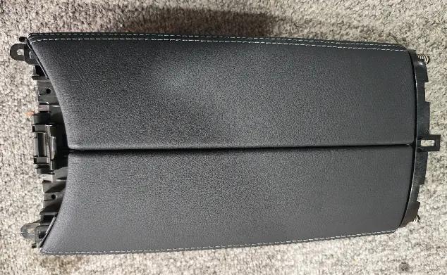
This flip-up cover closes the upper saddle-console compartment and provides access when raised. Confirm the latch and finish with the console base.
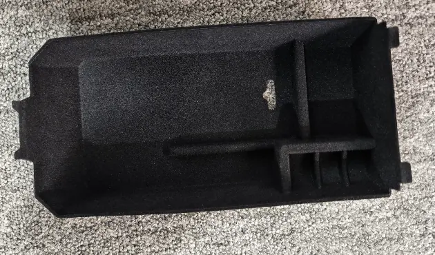
This divider organizes the inside of the saddle console by separating its storage areas. Confirm it matches the selected base and cupholder layout.
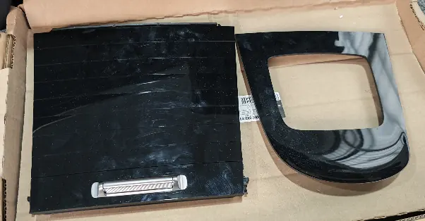
This sliding cupholder holds drinks in the updated centre-console area. Confirm its position and compatibility with the listed console base.
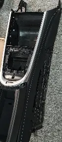
This base is the main support for the 465-style saddle-console components, including its covers and fittings. Confirm the full matched set.
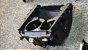
The standard cupholder holds drinks but, as the source specifies, does not include heating or wireless charging. A higher-spec version may need a different harness.
Covers adapt the listed dashboard sections; brackets mount the HU7 and instrument computers.
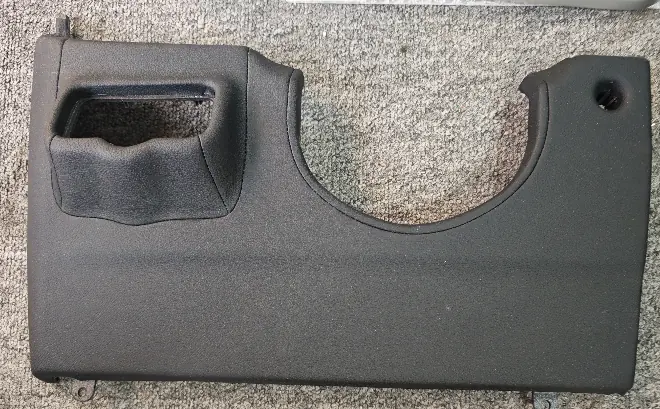
This cover adapts the dashboard trim around the headlight-switch position for the W464-to-W465-style layout. Confirm the vehicle-side fit and finish.
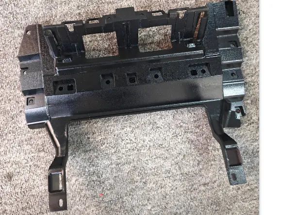
This cover finishes the centre dashboard base area in the W464-to-W465-style layout. Confirm its mounting points and adjoining trim.
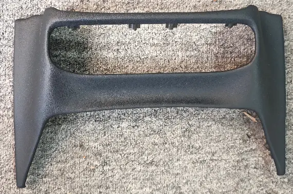
This cover surrounds the climate-control panel in the revised dashboard. Match it with the selected switch and air-vent panel.
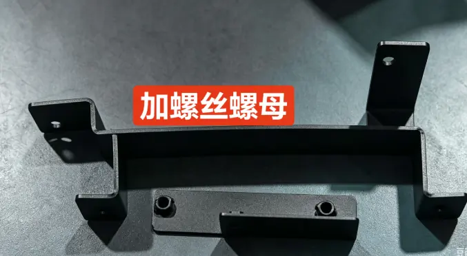
This bracket positions and supports the HU7 head unit behind the revised dashboard layout. Confirm mounting points for the exact vehicle.
Source photo shared with the custom instrument-computer bracket.
This bracket supports the instrument computer in its revised mounting position. Confirm the bracket and computer as a VIN-matched pair.
Source photo shared with the custom HU7 head-unit bracket.
Get a vehicle-specific parts check
Send your VIN, model year and current interior photos. We’ll confirm which listed parts apply, the final kit contents and the quotation before you order.